Dual-Axis Solar Tracker
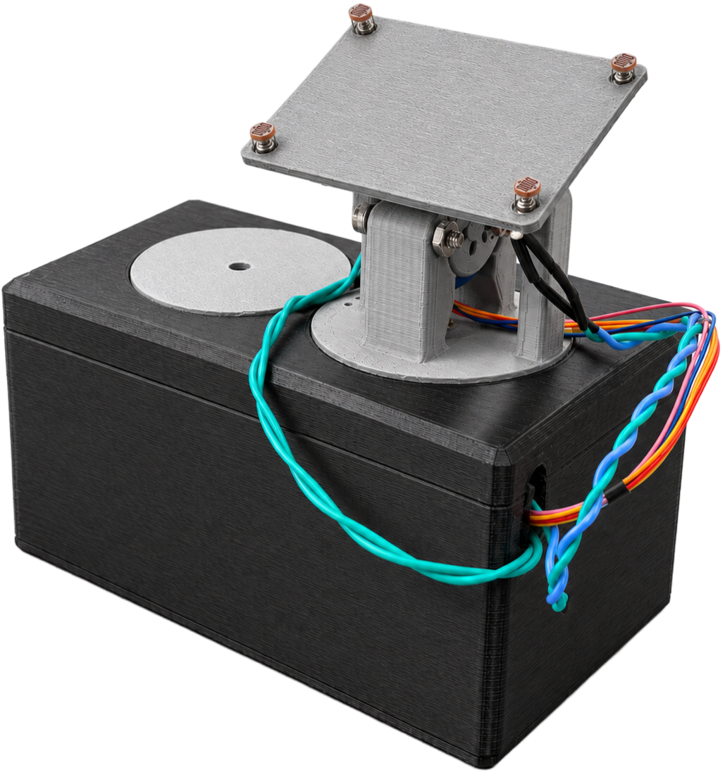
A two-axis solar panel that finds light on its own.
The build went through two full iterations. The first followed a conventional approach: more sensors, absolute position feedback, and a intuitively structured scan, but hardware failures during testing forced a redesign.
Iteration 1 - Initial Design
Potentiometer feedback, four-point scan
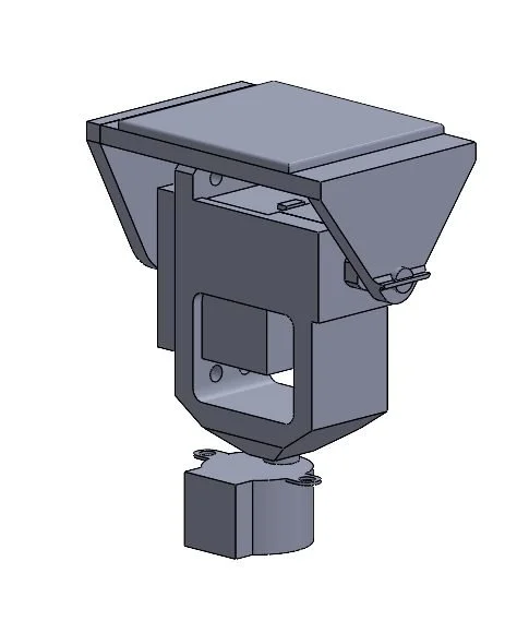
This concept was developed in CAD, with individual subsystem components tested independently and a 3D printed prototype created of the fully assembled system.
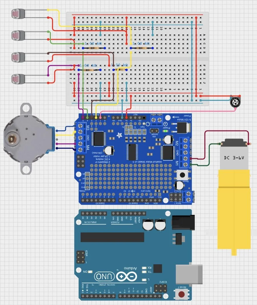
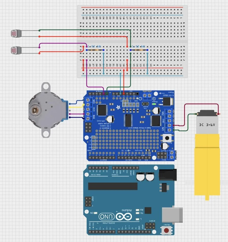
The stepper motor carried the full housing, DC motor, potentiometer, panel, and photoresistors — inspired by designs found during market analysis. A DC motor handled azimuth (yaw), geared to a potentiometer through a pulley for absolute angle feedback; a stepper handled altitude (pitch). Four photoresistors, wired as voltage dividers with 1 kΩ resistors, fed the Arduino's analog inputs through an Adafruit Motor Shield.
Control logic swept each axis through its full range, logged a summed sensor reading at every step, and returned to whichever angle had produced the strongest signal — a scan-then-return strategy rather than continuous tracking.
Issues Identified
Motor shield couldn't read analog pins 4 and 5
Two of four photoresistors were non-functional
Potentiometer was faulty
Design susceptible to stress concentrations at the base
Design susceptible to rotational instability
Initial circuit design
| Component | Qty | Role |
|---|---|---|
| Arduino Uno | 1 | Microcontroller |
| Adafruit Motor Shield V3 | 1 | Motor driver, mounted on Arduino |
| Photoresistors | 4 | Light sensing (TL, TR, BL, BR) |
| 1 kΩ resistors | 4 | Voltage dividers, one per photoresistor |
| 10 kΩ, 10-turn potentiometer | 1 | Azimuth position feedback, using DC motor & 1:1 pulley |
| 6V DC motor | 1 | Azimuth (yaw) rotation, on M1 |
| 5V Stepper motor | 1 | Altitude (pitch) tilt, on M3/M4 |
| Breadboard | 1 | Sensor and voltage-divider wiring |
| Pulley system | 1 | Mechanically links potentiometer to DC motor shaft |
Iteration 2 - Final Design
Weight moved to the base, focus moved to software
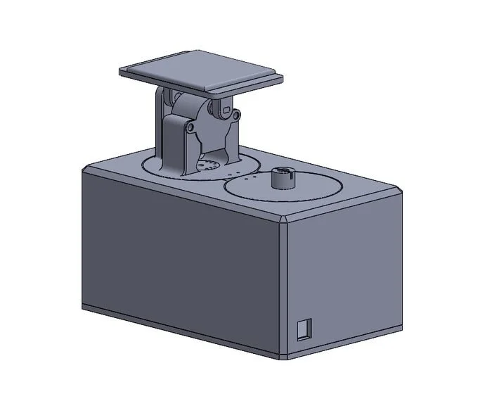
Building on shortcomings identified in Iteration 1, we re-evaluated the system architecture and selected components to mitigate known failure modes.
Because the previous design would struggle to support the assembly's weight on the stepper motor, the heavier azimuth rotation was assigned to a DC motor with greater load-carrying capability, while the stepper motor was reserved for the lighter altitude axis.
To improve packaging and serviceability, all electronics were consolidated into a single base enclosure with dedicated cable-routing paths for the photoresistors, breadboard, and Arduino.
Testing revealed unreliable sensor feedback due to a failed potentiometer and two non-functional photoresistors. In response, positional feedback was removed from the control strategy, and the remaining photoresistors were repositioned to opposite corners of the panel. This configuration enabled the controller to use differential light intensity measurements to determine tracking direction, allowing the system to maintain functionality despite reduced sensor availability
The algorithm changed as much as the hardware
When the potentiometer failed, that dependency became the system’s central failure point: we could no longer establish a calibrated relationship between commanded angle and sensor output, making it impossible to map a known angular position to a corresponding photoresistor reading. The solution therefore required replacing position-based control with a sensor-feedback-driven search algorithm that could operate without absolute angular feedback.
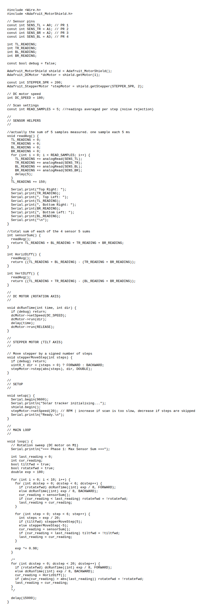
The revised controller implements a coordinate-descent hill-climbing algorithm over the tracker’s two rotational degrees of freedom. Rather than estimating or storing absolute position, the controller evaluates the quality of each incremental motion using the aggregate photoresistor response.
At every evaluation point, each of the four photoresistors is sampled five times with 5 ms spacing, and the samples are summed to reduce the influence of short-term measurement noise. These four averaged signals are then combined into a single objective function, the total sensor sum, representing the overall incident light intensity:
S = TL + TR + BL + BR
The controller first searches along the DC-motor rotation axis. It applies a timed rotational increment, measures the resulting sensor sum, and compares it against the previous measurement. If the new value is lower, the algorithm reverses the motor direction; if it increases, the controller continues in the same direction.
It then performs an analogous search along the stepper-driven tilt axis, again reversing direction whenever an incremental movement decreases the objective function. By alternating between rotation and tilt rather than optimizing both simultaneously, the controller performs a form of coordinate-wise optimization, progressively moving toward a local maximum in received light without requiring an encoder or potentiometer.
The search also incorporates a coarse-to-fine step-size schedule. The control parameter begins at 180 and is multiplied by 0.98 after each outer iteration, producing a 2% exponential reduction in the effective search scale. Early iterations therefore prioritize rapid convergence toward the high-illumination region, while later iterations make progressively smaller corrections to refine alignment and reduce oscillation around the optimum. The result is a feedback controller that effectively estimates the direction of the optical gradient from successive measurements rather than explicitly calculating angular position.
Importantly, this architecture shifts the system from position-based control to measurement-based optimization: the tracker does not need to know where it is, only whether its most recent perturbation improved the objective function. This allowed the remaining hardware—two photoresistors, one DC motor, and one stepper motor—to provide sufficient feedback for autonomous two-axis alignment despite the loss of the potentiometer and two photoresistors.
Final circuit design
| Component | Qty | Role |
|---|---|---|
| Arduino Uno | 1 | Microcontroller (unchanged) |
| Adafruit Motor Shield V3 | 1 | Motor driver (unchanged) |
| Photoresistors | 2 | Light sensing, repositioned to diagonal corners |
| 1 kΩ resistors | 2 | Voltage dividers, one per remaining photoresistor |
| 6V DC motor | 1 | Azimuth rotation, on M1 (unchanged) |
| 5V Stepper motor | 1 | Altitude tilt, on M3/M4 (unchanged) |
| Breadboard | 1 | Sensor wiring (unchanged) |
Results
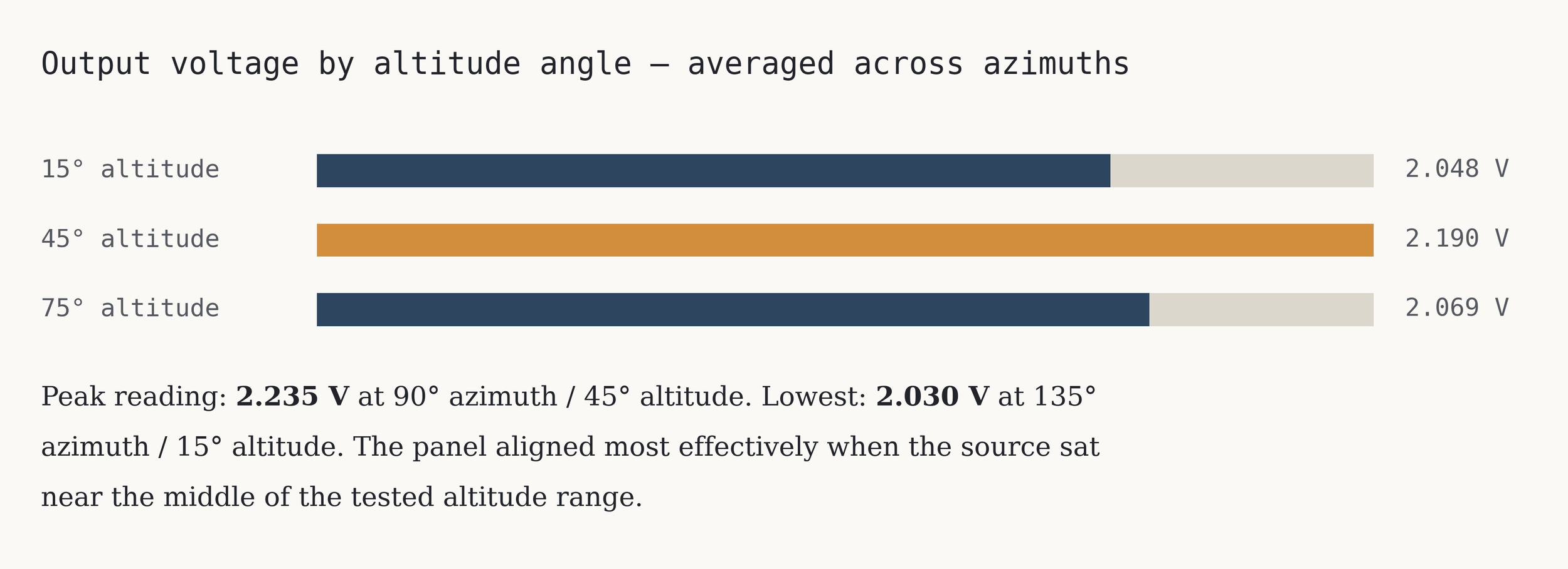
Qualitative tracking accuracy — 9/9 positions
| Azimuth | 15° alt | 45° alt | 75° alt |
|---|---|---|---|
| 45° | ✓ | ✓ | ✓ |
| 90° | ✓ | ✓ | ✓ |
| 135° | ✓ | ✓ | ✓ |
All nine tested positions aligned.
Tested at 9 combinations of azimuth (45° / 90° / 135°) and altitude (15° / 45° / 75°)
What we'd change next
Further Structure Optimization
The housing was functional but larger and less rigid than the 12 × 20 cm envelope required. Skeletonizing the footprint (via iterative FEA) and stiffening the mount between the DC motor and the panel assembly would cut flex during rotation, drop mass, and reduce settling oscillation.
Utilize Limit Switch
The kit included a limit switch that our final build never wired in, leaving azimuth travel bounded only by the software loop count. Adding it would cap rotation before the sensor cables wrap and give the tracker a repeatable home reference at startup.
Two of Four Sensors Down
Hardware failures left only one diagonal pair of photoresistors, so both axes were inferred from a single differential reading. Restoring a full symmetric quadrant, with each sensor shaded from ambient light, would sharpen directional resolution on yaw and pitch independently.